Homex

    光学機器

  • 光学機器 >
  • テレセントリックレンズ
  • 360°光学機器
  • マクロ光学機器
  • 固定焦点
  • オプトエンジニアリング赤外線光学機器
  • 補償光学
  • ライト

  • ライト >
  • LED点灯
  • LEDパターンプロジェクター
  • Lighting KITs
  • カスタムライト
  • カメラ

  • カメラ >
  • エリアスキャンカメラ
  • HR area scan cameras
  • HR line scan cameras
  • ソフトウェア

  • ソフトウェア >
  • FABIMAGE
  • TCLIB Suite
  • 360LIB Suite
  • Horus
  • アクセサリー

  • アクセサリー >
  • マウンティング機器
  • レンズのアクセサリー
  • 軽量アクセサリー
  • パターン
  • コントローラー&電力供給
  • ケーブル&電子部品
  • スペアパーツ
  • Other products
  • ビジョンシステム

  • ビジョンシステム >
  • ALBERT®
  • PENSO®
  • PENSO® KIT case
  • 会社

  • 会社 >
  • 光学イメージングテクノロジー
  • OE for the future
  • Who we are
  • 革新の歴史
  • 品質への尽力
  • Joint ventures
  • Where we are
  • Legal
  • カンパニーアウォード
  • 企業ビデオ
  • サービス

    Industries

    基礎

    リソース

    サポート

    キャリア

    プレスレビュー

    お問い合わせ

    EXE Training

  • jp
    • English
    • Deutsch
    • Italiano
    • Français
    • Español
    • 中文
    • 中文 (繁體)
    • 한국어
    • Pусский
会社
サービス
Industries
基礎
リソース
サポート
キャリア
プレスレビュー
お問い合わせ
Training
光学機器
ライト
カメラ
ソフトウェア
アクセサリー
ビジョンシステム
  • ホーム
  • ライト
  • LED点灯
  • LTCLHP CORE PLUS series

LTCLHP CORE PLUS series

大規模なFOVシステム用の省スペースのテレセントリック照明器

Catalog 2019

ニュース

概略

モデル

ダウンロード

関連するもの

技術情報

メディアギャラリー

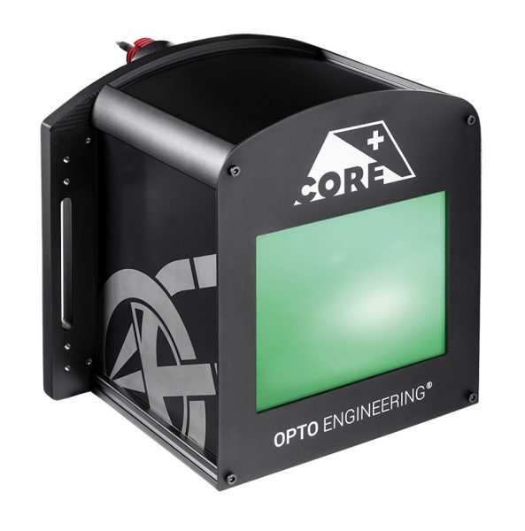
LTCLHP CORE PLUS テレセントリック照明器は、狭いスペースで広い領域を照らすように設計されています。市場にある他のテレセントリック照明よりも最大40%短くなっています。

テレセントリックレンズの長さと作動距離は、ビジョンシステムのサイズに大きく影響します。 作動距離範囲は、測定システムを可能な限りコンパクトにするために最適化されており、システム全体の寸法を最大で半分まで削減できます。

超コンパクトなフォームファクタにより、一般的な拡散バックライトの代わりに、classisテレセントリックライトが収まらないCORE PLUSコリメート照明を簡単に統合でき、システムのパフォーマンスが向上します。

LTCLHP CORE PLUSライトは、スマートな統合のために設計されています。 取り付けフランジが組み込まれているため、追加のクランプは不要です。

キーの利点

  • 超小型フォームファクターの大きな照明領域
    LTCLHP CORE PLUSは、市場にある他のテレセントリックライトよりも最大40%短くなります。
  • ビジョンシステムのサイズを縮小する
    LTCLHP CORE PLUSテレセントリック照明器の作動距離は、システム全体の設置面積を削減するために最適化されています。
  • 測定システムのパフォーマンスを向上させます
    LTCLHP CORE PLUSイルミネーターをフラットバックライトの代わりに使用して、システムのパフォーマンスを向上させることができます。
  • スマートな統合
    LTCLHP CORE PLUS照明器は、追加のクランプなしで簡単に統合できるように取り付けフランジを統合しています。
  • システムのコンパクトさは競争上の優位性です
    業界では、より小さなビジョンシステムまたは測定機が好まれています。

Advantages

Save more

• Lower manufacturing cost due to less material employed
• Cost of mounting is reduced as no addictional clamps are needed
• Less space required for storage and use
• Lower shipment expenses due to smaller size
• Lower transportation risks

Sell more

• A smaller system leads to more sales

テレセントリックライト
LTCLCP23144のメイン前面画像
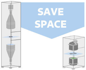
Comparison of precision measurement systems with “classic” telecentric lens
and light vs. CORE PLUS telecentric lens and light.

Comparison of precision measurement systems with “classic” telecentric lens and light vs. CORE PLUS telecentric lens and light.


Optical specs Electrical specifications Mechanical specifications


Device power ratings LED power ratings Dimensions
Part number Light color, wavelength
peak
Minimun
beam shape
dimension
Working
distance
range
DC voltage Power cons. Max LED fwd
current
Forward voltage Max pulse current A B C


min max

typ. max


(mm x mm) (mm) (V) (V) (W) (mA) (V) (V) (mA) (mm)

1 2 3 4
5 6 7 8 9 10
LTCLCP144-GSpace-saving telecentric illuminator for LARGE FOV systems, minimun beam shape dimension 165 x 120 mm, green green, 520 nm 165 x 120 170 - 350 12 24 < 2.5 350 3.3 4 2000 332.0 302.5 310.5 購入
LTCLCP192-GSpace-saving telecentric illuminator for LARGE FOV systems, minimun beam shape dimension 220 x 160 mm, green green, 520 nm 220 x 160 230 - 450 12 24 < 2.5 350 3.3 4 2000 410.4 344.1 359.3 購入
LTCLCP260-GSpace-saving telecentric illuminator for LARGE FOV systems, minimun beam shape dimension 265 x 200 mm, green green, 520 nm 265 x 200 270 - 500 12 24 < 2.5 350 3.3 4 2000 425.3 396.7 421.0 購入

最後の更新: 2020-02-28

ノート

  1. Opto Engineering® recommends green light for high precision measurement applications.
  2. Beam shape is not circular.
  3. Working distance: distance between the front end of the mechanics and the object. Set this distance within +/- 5% of the nominal value for maximum resolution and minimum distortion.
  4. Tolerance ± 10%.
  5. Used in continuous (not pulsed) mode.
  6. At max forward current.
  7. Tolerance is ±0.06V on forward voltage measurements.
  8. At pulse width <= 10 ms, duty cycle <= 10% condition. Built-in electronics board must be bypassed (see tech info).
  9. Maximum dimension of the clamping flange.
  10. Nominal value, with no spacers in place.

技術文書

データ表

(最後の更新::2020-02-28)
XLS
Brochure CORE PLUS Family

互換性のある製品

serie

TC CORE PLUS series

Ultra compact LARGE FOV bi-telecentric lenses for matrix detectors up to 2/3”

serie

TC3MHR-TC5MHR CORE PLUS series

最大4/3インチのマトリックス検出器用の超小型大型FOVテレセントリックレンズ

serie

LT2BC series

均一性の高い連続LEDバックライト

serie

LTBPシリーズ

ハイパワーストロボLEDバックライト

serie

LTBCシリーズ

連続LEDバックライト

serie

LTDV1CH-17V

ストロボコントローラー 1 チャンネル 可変電流 5 mA - 17A

仕様

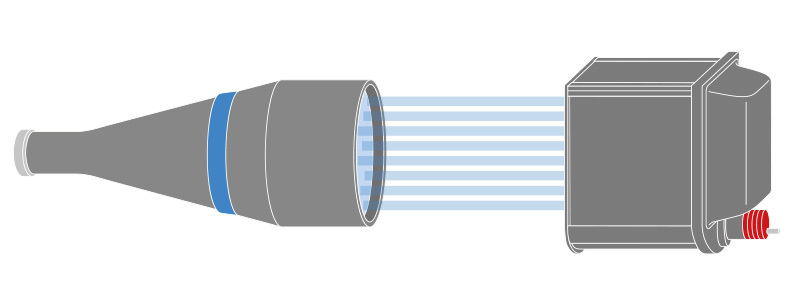
TC CORE PLUS telecentric lens.

TC CORE PLUS telecentric lens.

Setup instructions 1

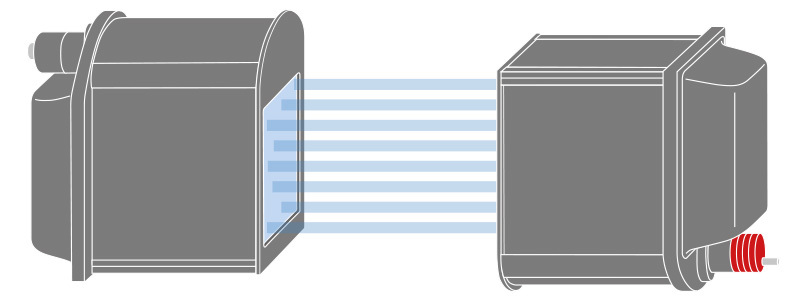
To build a telecentric measurement setup it’s necessary to position a LTCLHP CORE telecentric illuminator upside down with respect to the TC CORE PLUS telecentric lens.

LTCLHP CORE PLUS telecentric illuminator

LTCLHP CORE PLUS telecentric illuminator

Setup instructions 2

LTCLHP CORE PLUS telecentric illuminator is also a perfect solution when coupled with classic telecentric lenses (e.g. TC series).

アプリケーションの例

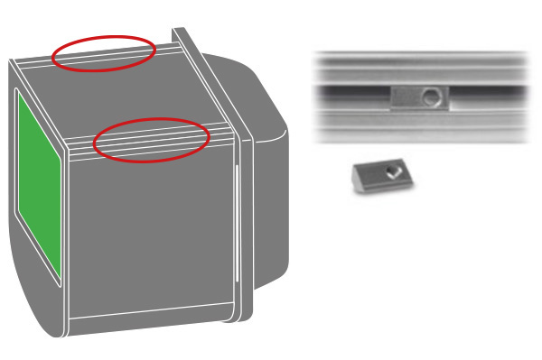
Integrated extruded aluminum profiles with M5 T-slot nuts allow for easy and cost-effective mounting.

Integrated extruded aluminum profiles with M5 T-slot nuts allow for easy and cost-effective mounting.

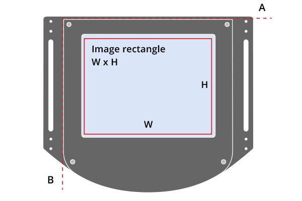
The width of the beam rectangle is aligned along the A axis.
The height of the beam rectangle is aligned along the B axis.

The width of the beam rectangle is aligned along the A axis. The height of the beam rectangle is aligned along the B axis.

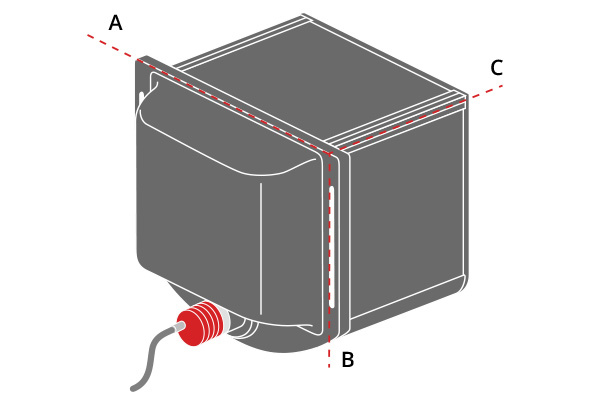
A, B an C indicate the mechanical
dimensions of the illuminator.

A, B an C indicate the mechanical dimensions of the illuminator.


Vimeoチャンネルでもっとビデオを

  • TC CORE PLUS telecentric lens.
  • LTCLHP CORE PLUS telecentric illuminator

  • Integrated extruded aluminum profiles with M5 T-slot nuts allow for easy and cost-effective mounting.
  • The width of the beam rectangle is aligned along the A axis.
The height of the beam rectangle is aligned along the B axis.
  • A, B an C indicate the mechanical
dimensions of the illuminator.
会社 & リソース
光学イメージングテクノロジー OE for the future Who we are 革新の歴史 品質への尽力 Joint ventures Where we are Legal カンパニーアウォード 企業ビデオ 2Dそして3Dモデル   イメージギャラリー   ビデオギャラリー 利用法別にオプトエンジニアリング製品を探す 用途ノート 基礎  よくあるご質問 プレスレビュー  オプトエンジニアリングでの業務

Opto Engineering Copyright © 2015 - 2021 | P. IVA 02011230204 | All rights reserved | Terms of use | クッキー&プライバシーポリシーの使用

Design & development by Opto Engineering → SEO and consulting by Dipiemme Studio

  • ENWHP Rete Lombardia
  • ISO 9001:2015
  • TuvRheinald Certified
  • This website is hosted Green - checked by thegreenwebfoundation.org